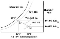
during evaporative cooling as
shown on a psychrometric chart.
Brian R. Strobel
Extension Associate
Richard R.
Stowell
Assistant Professor
Ted H. Short
Professor
|
|---|
| Figure 1. Changes in air properties during evaporative cooling as shown on a psychrometric chart. |
Summer heat can cause indoor conditions to become much hotter than desired. Evaporative cooling is one way to reduce temperatures inside buildings. As water evaporates, it absorbs energy from the surrounding environment. A well-maintained ventilation system with evaporative cooling can reduce incoming air 10 to 20°F. Cooler indoor temperatures can improve the environment for plants and animals, plus significantly improve working conditions for employees.
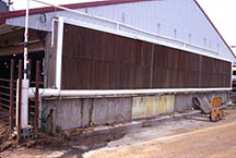
Evaporative cooling systems lower air temperature using mists, sprays, or wetted pads. Introducing water into ventilation air increases relative humidity while lowering the air temperature (see Figure 1). This fact sheet specifically describes systems that utilize wetted pads (see Figure 2).
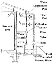
The typical evaporative pad cooling system (shown in Figure 3) draws outside air into the building through wet vertical pads. The major components of this system are: pad media, water supply, pump, distribution pipe, gutter, sump, and bleed-off line. As air flows past the moist pad surfaces, some of the moisture evaporates into the air stream. Heat is withdrawn from the air during this process and the air leaves the pad at a lower temperature with higher moisture content.
Water is continuously circulated over and through the pad cells during operation. A pump transports water from a sump through a filter and to a distribution pipe along the top of each pad. A gutter collects unevaporated water that drains from the bottom of each pad. Water can be recycled as long as salt or minerals do not collect noticeably on the pads.
 |
|---|
| Figure 2. Building equipped with an evaporative pad cooling system. |
Only part of the water flowing over the pad material is evaporated. Water temperature does not have a great effect on the cooling achieved. Recommended minimum water flow rates through vertically-mounted pads and sump capacities are listed in Table 1.
The excess water that is collected from the pad should be screened to remove pad fibers and other debris before the water is returned to the sump (Figure 3). A 50-mesh inclined screen mounted below the return flow is generally effective. Install removable caps on the ends of water distribution pipes to allow for bi-monthly flushing and convenient access.
The salt and mineral concentrations of water in a pad system increase as water evaporates. If the mineral content of the water supply is high, a bleed-off system is essential to prevent mineral deposits in the pad. A continuous water bleed-off rate of 0.05 gpm for every 1,000 cfm (0.02 L/min per m3/s) of airflow is recommended.
A pad system should match the ventilation needs of a facility. Most pads are made of either aspen fiber or cellulose (Tables 1 and 2). A cellulose pad typically needs more air and water flow than does an aspen pad. More evaporation can take place through a 6-inch pad than a 4-inch pad.
Place pads continuously along the entire side or end of a building so that they are opposite the ventilation fans to provide uniform ventilation. Pad area for a wall-unit evaporative cooler is calculated by dividing the required airflow by the recommended face velocity (see Table 2) through the pad. A rule of thumb is to have 250 ft/min of air flow through a 4-inch-thick pad.
A room has a 48-inch fan (0.5 Hp) that will deliver 14,600 cfm against a static pressure of 0.10 in. H20 for warm-season ventilation. A 4-inch aspen pad will be mounted horizontally in the endwall. The pad is 11.75 ft long x 8 ft high. What is the recommended air face velocity for this pad and is one pad sufficient for this building?
 |
|---|
| Figure 3. Wall-mount evaporative coolingsystem (MWPS-1,p. 635.1). |
Solution: The recommended air face velocity (from Table 2) is 200 ft/min. The pad area required for complete cooling is found by dividing the required air flow rate by the recommended air face velocity. For this case, 14,600 ft3/min ÷ 200 ft/min = 73 ft2. The total pad area supplied is 94 ft2 (11.75 ft x 8 ft) which is greater than the 73 ft2 required, so one pad provides adequate face area.
An effective evaporative cooling pad system should cool incoming air to within 3.5°F (~2°C) of its wet-bulb temperature. Air temperature then increases from the pads to the exhaust fans as mixing occurs and heat is added as air passes through the room. Periodically check air face velocities through pads when all room fans are operating to ensure that the desired air flow rate is being delivered through the pads. Air should flow smoothly from the pad into the room without noticeable turbulence.
Greenhouse designs usually specify 0.75 to 1 air change per minute as a maximum ventilation rate for buildings 100 feet to 150 feet long. Summer ventilation needs for animals may vary from 0.1 to more than 1 air change per minute depending on the species and the ventilation system that is selected. An air change is represented by the volume of air in a room.
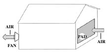
A pad-and-fan cooling system typically consists of axial-flow exhaust fans installed in one wall and correctly-sized wetted pads placed along the opposing wall (Figure 4). The fans exhaust air from the building and draw in fresh air through the pads. Fans should be located in the side of the building that is downwind of the summertime prevailing winds. To function properly, the fans must be able to develop a slight vacuum inside the building. This requires that the remainder of the building be reasonably airtight. For example, all doors must be kept closed.
| Table 1. Recommended water flow rates and sump capacities for vertically-mounted cooling pad materials. | ||||
|---|---|---|---|---|
| Pad type and thickness | Minimum water flow rate per unit length of pad |
Minimum sump capacity per unit pad area | ||
| gpm/ft | L/min'm | gal/ft2 | L/m2 | |
| Aspen fiber | ||||
| 2 to 4 in (50 to 100 mm) | 0.3 | 4 | 0.5 | 20 |
| Aspen fiber, desert conditions | ||||
| 2 to 4 in (50 to 100 mm) | 0.4 | 5 | 0.5 | 20 |
| Corrugated cellulose | ||||
| 4 in (100 mm) | 0.5 | 6 | 0.8 | 30 |
| Aspen fiber | ||||
| 6 in (150 mm) | 0.8 | 10 | 1.0 | 40 |
| Table 2. Recommended air face velocities through several different pad materials. | ||
|---|---|---|
| Pad type, thickness in (mm) |
Air face velocity through pad* | |
| ft/min | m/s | |
| Aspen fiber, 2 to 4 in (50 to 100 mm) | ||
| mounted vertically | 150 | 0.75 |
| mounted horizontally | 200 | 1.00 |
| Corrugated cellulose, 4 in (100 mm) | 250 | 1.25 |
| Corrugated cellulose, 6 in (150 mm) | 350 | 1.75 |
| *Velocity should be increased by 25% when limited by construction space. | ||
If the air inlet opening is larger than the pad, place the pad so that excess open area is distributed uniformly around the pad. Pad height should not exceed 8 ft (2.5 m). If the pad height exceeds that of the inlet, the pad should be set back from the wall opening a distance equal to half the height difference. Construct inlets so they can be easily closed without removing the pads.
Three stages of control are preferable to meet the cooling requirements of most controlled-environment buildings. These stages are designed for hot, mild, and cold conditions. Water is circulated through the pad system only during hot conditions.
Wire a control switch in parallel with each control stage to permit manual control when desired. Also, install a safety disconnect switch near each fan and pump. Locate thermostats at plant or animal height, if possible. Thermostats and other control sensors should be near the center of the room and away from unrepresentative hot or cold air streams. If the building is divided into zones, locate a control sensor near the center of each zone.
Set the ventilation thermostat at least 10°F above the heater thermostat setting to prevent simultaneous operation. Air inlet controls should operate on the same thermostat that activates the fan system. Control sensors should be capable of withstanding extremely humid and dusty conditions.
Water should be screened before it is returned to the sump, as already described. Check the screen regularly to ensure that it is reasonably free of debris. Cover the sump to keep out debris.
Pad life can be extended by:
Algae require light, moisture, and nutrients to survive. To control algae:
Always read the manufacturer's label to determine the correct dosage. As a check, use this equation for determining disinfectant dosages (note that 78 is a conversion factor):
| concentration X sump capacity | __ ppm X __ gal | |||
| dose = |
|
= |
|
= ____ fl oz |
| percent active ingredient X 78 | _____ X 78 |
For instance, with a sump capacity of 1,000 gallons, an algaecide with 10% active ingredient, and a desired concentration of 40 ppm, the disinfectant dosage is:
| 40 ppm X 1,000 gal | ||
| dose = |
|
= 51 fl oz |
| 10 X 78 |
Air moving through a wetted pad picks up moisture, and is cooled in the process. A properly designed and maintained pad-and-fan evaporative cooling system will effectively cool ventilation air without wetting a room and its contents. Proper design supplies: 1) water impartially over and through the pad area and 2) the desired air flow through the room. Good maintenance practices preserve the pad and keep the water delivery system in proper working condition.
 |
|---|
| Figure 4. Typical location of pads and ventilating fans. |
Acme Engineering & Mfg. Corp. 1975. The Greenhouse Climate Control Handbook. Muskogee, OK.
ASAE. 1991. Heating, Ventilating, and Cooling Greenhouses (EP406.1). ASAE Standards. 38th edition. pp. 490-493. American Society of Agricultural Engineers. 2950 Niles Rd. St. Joseph, MI.
ASHRAE. 1977. Handbook of Fundamentals. Fourth Printing. Ch. 9. American Society of Heating, Refrigerating, and Air Conditioning Engineers. New York, NY.
Czarick, M. and M. Lacy. 1998. Evaporative cooling pads reduce incoming air temperature. Poultry Times. May 4, 1998. pp. 25. Gainesville, GA.
MWPS-1. 1983. Structures and Environment Handbook. Eleventh Edition. pp. 602.1-602.10. Midwest Plan Service, Iowa State University, Ames, IA.
NRAES. 1992. Greenhouse Engineering. pp. 79-87. Northeast Regional Agricultural Engineering Service. Ithaca, NY.
Wark, K. 1988. Thermodynamics. 5th edition. pp. 434-457. McGraw Hill. New York, NY.
Wilson, J. L., H. A. Hughes, and W. D. Weaver, Jr. 1983. Evaporative cooling with fogging nozzles in broiler houses. Transactions of the ASAE, Vol 26 (2): 557-561.
Reviewed by: Joe Beiler, Mercer Co. Extension; Steve Ruhl, Morrow Co. Extension; and Mike Lichtensteiger, Food, Agricultural, and Biological Engineering.